Showing posts with label Digital Electronics. Show all posts

Relays, Working principle of relay,


            Introduction:

An electrical relay is a switch which is under the control of another circuit. A classic example of an electrical relay is the system used to start a car. When someone turns an ignition key, the ignition does not interact directly with the car battery.

Recommendation for Future Work ,Results Validated By Theoretical Modeling and Development of Algorithm

Recommendation for Future Work:
          In the whole research work, attention was paid to simulate all the structures by commercial EM software Zeland IE3D. Investigations need to be justified experimentally by VNA and compared with simulated results.

Motivation, Reasoning and the Proposed Proposition of EBG structures and Application of Dumbbell shaped EBGS as BPF


Motivation, Reasoning and the Proposed Proposition of EBG structures


From the intensive literature survey it is clear that the inclusion of EBGSs / dumbbell shaped EBGSs improve the performance of microwave components and devices significantly. From the performance of novel 2-D EBG structures for microstrip lines it is obvious that the performance is hindered by the optimized value of FF.

Realization of Band Pass Filter (BPF) and Non-uniform EBGS


 Realization of Band Pass Filter (BPF)


Each type of filters has different type of applications in the field of microwave communication system. There is a well defined formula deduced from the Bragg’s condition for circular shaped EBGS.

Simple T-line and its performance, S-Parameter Performance of a microstrip T-line, Design of uniform circular PBGSs for Harmonic Suppression, Standard BPF, BPF on 2-D array of uniform circular PBGSs, BPF with dense 2-D uniform circular PBGSs, BPF with PBGSs under 50-ohm and central coupled lines


    Simple T-line and its performance:
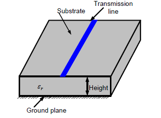
T-line is just a line with a defined length and width on the upper surface of the substrate which is created by removing copper coating from the surface except the desired region. The figure is shown below where the blue region is a typical T-line whose length is 100 mm and width is 2.2642 mm (calculated by PCAAD for 50Ω microstrip T-line where dielectric constant of the substrate is 2.45 and thickness is 31 mils).


Corrugated Surface and Metal Pad or High-Impedance Surface


Corrugated Surface


A corrugated surface is a metal slab into which a series of vertical slots are cut. The slots are narrow so that many of them fit within one wavelength across the slab. Each slot can be regarded as a parallel plate transmission line, running down into the slab, and shorted at the bottom.

Microwave Filter design, Applications to BPF ,Application to LPF, Application to dual stopband filter, Band-pass filters


Microwave Filter design
              There is a vast amount of published literature on the design of microwave filters from which some are highly mathematical. Fortunately there are some relatively straight forward procedures which enable us to design certain useful classes of microwave filters. Filter designing using the image parameter method consist of a cascade of simpler two-port filter sections to provide the desired cutoff frequencies and attenuation characteristics but do not allow the specification of a frequency response over the complete operating range.

Microwave Filters,Lumped - element LC filters , Planar filters, Coaxial filters, Cavity filters, Dielectric filters and Electro acoustic filters


Lumped - element LC filters
An LC tank circuit consisting of parallel or series inductors and capacitors is a best example of a simplest resonator structure. These LC tank circuits have the advantage of being very compact & small in size, but having the low quality factor of the resonators which leads to relatively poor performance. 


Figure: Commercial photograph of Lumped-element LC filters.

Introduction, Microwave filters, Filter and There are mainly four types of filters with respect to functions


  Microwave filters

   Introduction

          A filter is a two-port network used to control the frequency response at a certain pointin an RF or microwave system by providing transmission at frequencies within the passbandof the filter and attenuation in the stopband of the filter.
Microwave filters represent a class of electronic filter design to operate on signals in the MHz to GHz frequency ranges. This frequency range is the range used by most broadcast radio, television, wireless communications like Cell phone, Wi-Fi, Wi-Max and the most radio frequency and microwave devices will include some kinds of filtering on the signals transmitted or received.
Theoretical Background and Microwave Transmission lines Theories


 Introduction:

Recently EBGSs have occupied significant portions of microwave engineering literature to enhance the performance of many microwave devices and components. The nomenclature EBG is actually used in the optical communication. Recently they are scaled down to RF engineering. They are very old concepts in terms of periodic structures. EBG structures are periodic in nature.

Application of microwave engineering, Microwave Transmission lines and Microwave filters


            In microwave engineering high frequency and short wavelength make unique opportunities for the microwave systems. This is because of following consideration:
§  Antenna gain is proportion to the electrical size of the antenna. At higher frequencies, more antenna gain is therefore possible for a given physical antenna size, which has important consequences for implementing miniaturized microwave system.

Introduction of Frequency range of waves and Frequency Band Designation


  Introduction:

The microwave refers to an alternating current signals with frequencies between 300 MHz and 300 GHz with corresponding electrical wavelength between λ = c/f = 1m and λ = 1mm respectively. It is quite impossible to solve microwave network problem using standard circuit theory directly but standard circuit theory is an approximation of the broader theory of electromagnetism as described by Maxwell’s equations.

Gas Turbine Power Plant Modelling for Operation Training


           The $11.4 billion worth of non-aviation gas turbines produced in 2008, $9.6 billion—more than 80 percent—were for electrical generation (Langston, 2008). Particularly, in Mexico, about 15% of the installed electrical energy (no counting the electricity generated for internal consuming by big enterprises) is based on gas turbine plants (CFE web page), either working alone or in combined cycle power plants (and 8% produced directly by gas turbines) that offers an important roll in improving power plant efficiency with its corresponding gains in environmental performance (Rice, 2004).

The Biased p-n Junction


     An externally applied potential will alter the potential difference between the p- and n-regions. This in turn will modify the flow of majority carriers, so that the junction can be used as a “gate”. If the junction is forward biased by applying a positive voltage V to the p-region Fig. , its potential is increased with respect to the n-region, so that an electric field is produced in a direction opposite to that of the built-in field.

THE IGFET/MOSFET


The second (and most important) family of FETs are those known under the general title of IGFET or MOSFET. In these FETs, the gate terminal is insulated from the semiconductor body by a very thin layer of silicon dioxide, hence the title ‘Insulated Gate Field Effect Transistor,’ or IGFET. Also, the devices generally use a ‘Metal-Oxide Silicon’ semiconductor material in their construction, hence the alternative title of MOSFET.

ALTERNATOR UNIT REPAIR AND ALTERNATOR


Disconnect grounded cable at battery before removing or attaching battery cable at alternator output terminal. Otherwise, a tool shorted to the battery cable at the output terminal can quickly heat enough to cause a skin burn or damage the tool or cable.

Multiple Impulse Method (SIM/MIM)


       The Multiple Impulse Method is the most advanced cable fault prelocation method available.
Every cable fault that is either a high resistive or intermittent fault can not be indicated by means of the TDR method. The low voltage impulse sent out by the Time Domain Reflectometer is not reflected at the faulty position, as the fault impedance compared to the insulation impedance of the healthy part of the cable is not significantly lower.


Polymers ,Electrolyte and Organic


 Polymers

Polymeric materials, such as p- and n-dopable poly(3-arylthiopene), p-doped poly(pyrrole), poly(3-methylthiophene), or poly(1,5-diaminoanthraquinone) have been suggested by several authors [17–19] aselectrodes for electrochemical capacitors.

Classification of electrochemical capacitors


                    Electrochemical capacitors may be distinguished by several criteria such as the electrode material utilized, the electrolyte, or the cell design.With respect to electrode materials there are three main categories: carbon based, metal oxides and polymeric materials.